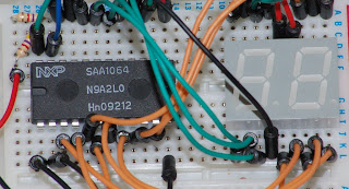
I was looking though the maplin catalog when I was in there a few days ago and I saw this little beauty, so I bought it.
So, having got the LED display I have to look at how to run it. It is a common anode display (common positive) so it works by the controller pulling the pins to ground.
There are three basic ways I can do this:
- I can connect the pins directly to the arduino, and use that to control the display.
- I could use two eight bit shift registers, one for each digit.
- I could use a dedicated micro controller.
A bit of browsing of the Farnell website revealed the SAA1064 7 Segment LED controller. It connects to the arduino via the I2C bus, so it only requires two pins. This solution doesn't require 16 resistors to function and only cost a couple of pound, so I decided: sod it.
I had a quick browse around the internet and other people had had success with this chip and the arduino so I set to connecting it up. I did discover that for reliable function of the I2C bus with the arduino you need to use two pull up resistors on the SDA and SCL (serial data and serial clock) lines (you can just see one of them on the left of the picture. There seems to be some confusion over this, I have read that the Wire library automatically turns on the interal pull-up on the arduino so that the resistors aren't required, but if I do this then the connection is tenuous at best, and can take many presses of the reset button before it works. I nearly threw the whole lot out of the window before I figured that out!
I look at the datasheet for the SAA1064 and in order to operate more that two digits you need to run the device in multiplex mode. In this mode the chip switches rapidly between two outputs, turning on two digits at a time. However for this to work you need a 2nf capacitor. Which I didn't have. So I started off by running the chip in two digit mode.
Or tired to. I did have a few issues getting the damned thing to work at all but this turned out to be because the I2C rate was set to 400hz and the chip will only work at 100hz. Having worked around these 'teething' issues I did eventually get it to work so I decided to get the required 2nf capacitor and another display. Bring on Farnell! The next day I received two LED displays and 10 2nf capacitors (which they shipped to be from Belgium. It must gave cost more to send that the parts cost and postage was free. Work that out.)
With the capacitor in place, and with the addition of a couple of transistors I finally manged to get the display to output four digits. The slight fuzzing on the picture is caused by the multiplexing. It is far too quick to be seen by the human eye, but it can be seen by the camera (The shutter was set to 1/60th of a second.)
Now, having got it working I decided that I need to write a library so that it will be easy to use it in the future.
The things I want to accomplish here are: denary (base 10) and hex (base 16) display of integer values, along with denary display of real values to a specified number of decimal places.
I did this and the resulting library can be downloaded here.
The next thing I want to do is to incorporate this onto a circuit board so that I can use it more easly in the future. Bring on EAGLE.
The first problem was that there isn't a part in the library for the SAA1064 (or at least, if there is then I can't find it) so I had to make one.
The schematic on the left is the result of about an hours work. it would have been much less if I didn't have to make part.
The next thing was to make a board layout. This should have been quite simple, but no! The problem wasn't so much with the layout itself, but with the manufacturing methods. I can't solder the LED displays to the top of the board because a) the LED displays sit flush with the board and b) it would be hard, even if they didn't sit close to the board.

So I used top exclusion areas to make the auto-router connect to all the components on the bottom layer. Then the second problem arose: The built in auto-router in EAGLE is rubbish and couldn't route the whole board, but never fear, for freerouting.net comes to the rescue.
The only problem now is that I don't have the equipment to make the board, so I will have to save my pocket money!
Next project: An I2C connected real-time-clock


